
TM 5-3805-261-23-2
HYDRAULIC PUMP ASSEMBLY AND MOUNTING REPLACEMENT - CONTINUED
0329 00
REMOVAL - CONTINUED
7.
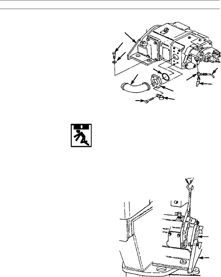
Remove four bolts (23) and washers (22) from mount-
ing bracket (24).
24
8.
Disconnect hose assemblies (14 and 15) from tee (16).
23
9.
Remove tee (16).
22
10.
Remove four bolts (19), clip (18), flange (17), tube
assembly (21), and preformed packing (20). Discard
preformed packing.
14
20
21
16
15
17
18
19
397-1473
11.
Position hydraulic pump assembly (4) on left side of pivot area. Slide pump and mounting bracket (24) as an assembly
from underneath cab into a position where sling can be attached.
WARNING
Use extreme caution when handling heavy parts. Provide adequate support and use assistance during proce-
dure. Ensure that any lifting device used is in good condition and of suitable load capacity. Keep clear of
heavy parts supported only by lifting device. Failure to follow this warning may cause injury or death to per-
sonnel.
NOTE
Hydraulic pump assembly weighs 159 lb (72 kg).
12.
Attach sling to pump (4) and mounting bracket (24) as
an assembly and take up slack.
13.
Remove pump (4) and mounting bracket (24) as an
assembly from machine.
14.
Place pump (4) on wood blocks.
4
24
397-1474
0329 00-3