TM 5-3805-261-23-1
SCARIFIER ASSEMBLY REPLACEMENT - CONTINUED
0264 00
REMOVAL - CONTINUED
2.
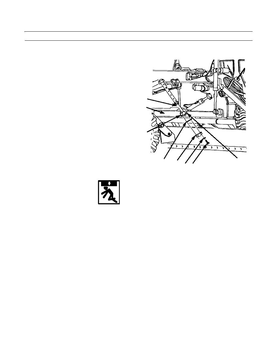
Position socket (6) of rod (8) on ball (5) of drawbar
and yoke assembly (7).
3.
Install spacer(s) (1), cap (2), two washers (3), and
bolts (4) to retain rod (8) on ball (5) of drawbar and
yoke assembly (7).
8
7
6
5
1
2
34
397-851
WARNING
Use extreme caution when handling heavy parts. Provide adequate support and use assistance during proce-
dure. Ensure that any lifting device used is in good condition and of suitable load capacity. Keep clear of
heavy parts supported only by lifting device. Failure to follow this warning may cause injury or death to per-
sonnel.
NOTE
Drawbar weighs 1010 lb (458 kg).
Steps 4 through 10 cover removal of the left drawbar. Follow these instructions for the right drawbar
connecting link.
0264 00-2


