TM 5-3805-261-23-1
OIL COOLER TO RELIEF VALVE AND HYDRAULIC
TANK LINES AND FITTINGS REPLACEMENT - CONTINUED
0250 00
INSTALLATION - CONTINUED
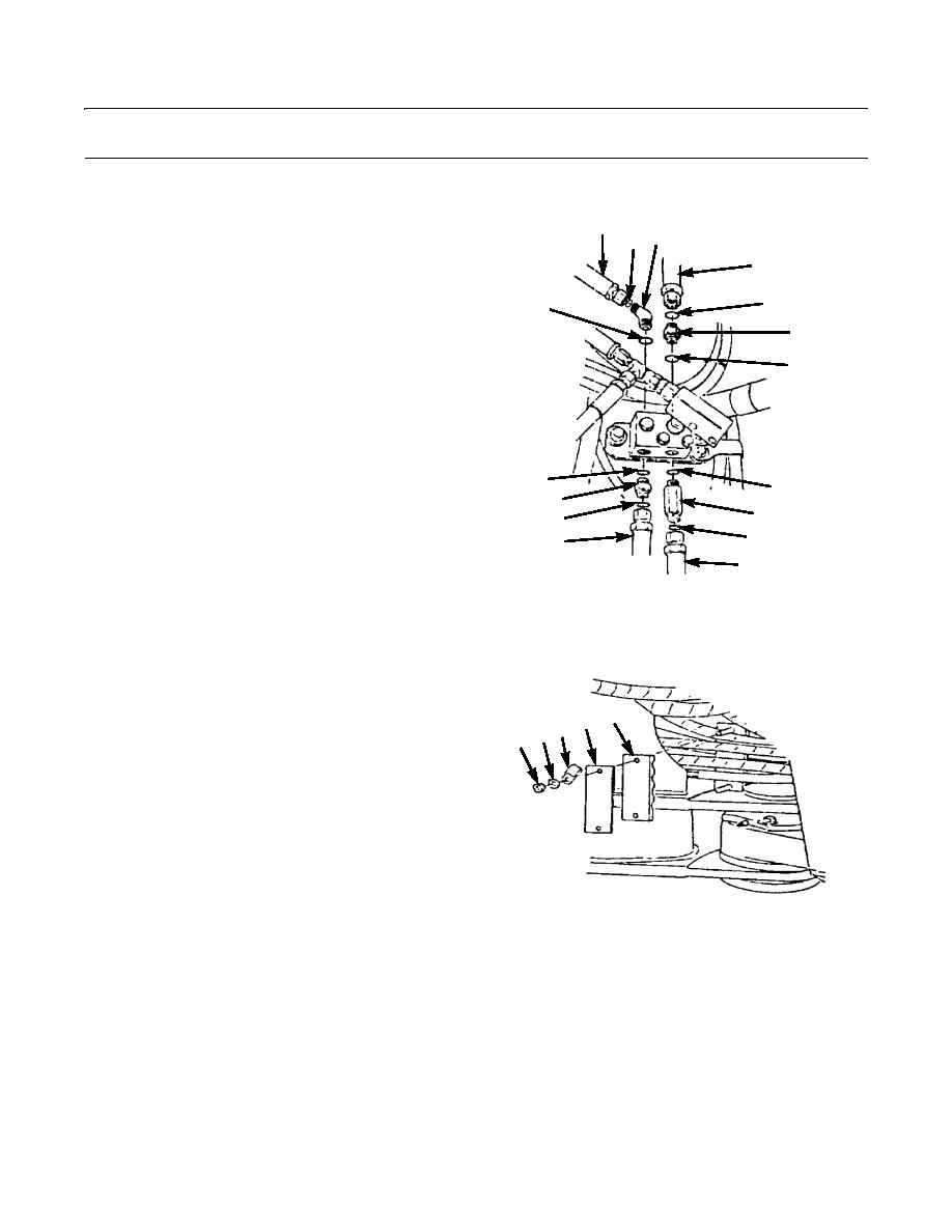
7.
Install new preformed packing (79) and elbow (69) to
80
top of hydraulic pump relief valve.
68 69
8.
Install new preformed packing (68) and connect hose
21
assembly (80) to elbow (69).
9.
Install new preformed packing (72) and connector
70
79
(71).
71
10.
Position hose assembly (21) to machine.
72
11.
Install new preformed packing (70) and connect hose
assembly (21) to connector (71).
12.
Install new preformed packing (73 and 78) and install
connectors (74 and 77) to bottom of hydraulic pump
relief valve.
13.
Position hose assemblies (35 and 39) to machine.
78
73
77
NOTE
74
76
Type II machines are equipped with quick-
75
35
disconnect fittings on hose assemblies (35
39
and 39).
397-1654
14.
Install new preformed pckings (75 and 76) and con-
nect hose assemblies (35 and 39) to connectors (74
and 77).
15.
Position clamp (67), plate (66), and clamp (65) under
hydraulic tank.
67
65 66
16.
Install two washers (64) and nuts (63).
63 64
397-1656
0250 00-9


