TM 5-3805-261-23-1
HYDRAULIC PUMP RELIEF VALVE MAINTENANCE - CONTINUED
0238 00
INSTALLATION - CONTINUED
2.
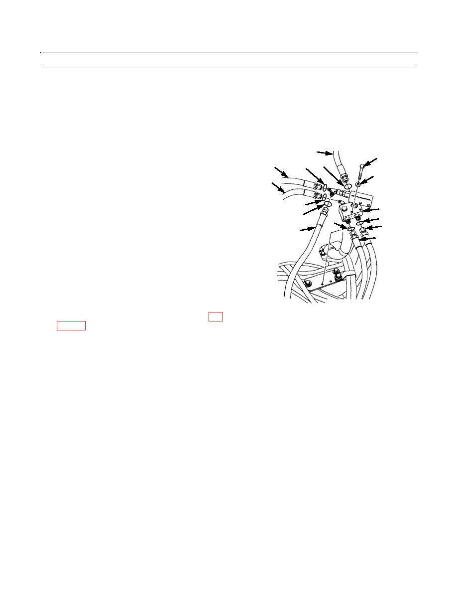
Install relief valve (6) assembly with two washers (5) and bolts (4).
3.
Install new preformed packing (13) and connect hose assembly (14).
NOTE
For Type II machines, hose assemblies (11, 10, and 8) are equipped with quick connect fittings.
4.
Install new preformed packing (12) and connect hose
2
4
assembly (11).
15
3
1
5
5.
Install new preformed packing (9) and connect hose
14
assembly (10).
6.
Install new preformed packing (7) and connect hose
13
assembly (8).
6
12
7
7.
Install new preformed packing (3) and connect hose
10
8
assembly (2).
11
9
8.
Install new preformed packing (1) and connect hose
assembly (15).
9.
Start engine (TM 5-3805-261-10).
10.
Operte control levers. Cycle system through at least
five full-travel movements to bleed air from system.
11.
Stop engine and check for leaks.
397-673
12.
Check hydraulic oil level and fill as necessary (WP
END OF WORK PACKAGE
0238 00-6


