TM 5-3805-261-23-1
OPERATOR'S PANEL CONSOLE REPLACEMENT - CONTINUED
0193 00
REMOVAL
1.
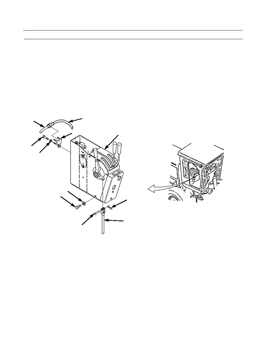
Remove cotter pin (5), clevis pin (7), and disconnect linkage rod (6) from right side of operator panel console (4). Dis-
card cotter pin. Lay linkage rod to one side.
2.
Remove four bolts (8) and washers (9).
3.
Separate wiring harness (2) from bracket (3) at rear of operator panel console (4).
NOTE
Tag wiring harnesses before disconnecting to aid in installation.
4.
Disconnect wiring harness (2) from wiring harness (1).
5.
Remove four bolts (11), washers (10), and bracket (3).
2
1
3
4
11
10
9
8
5
6
7
397-612
0193 00-2


