TM 5-3805-261-20
STEERING MAINTENANCE.
11-6.
Supplemental Steering Check Valve. (Sheet 2 of 3)
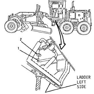
REMOVAL
1.
Remove three bolts (1) and washers (2,
Figure
11-46)
from
left
side
under
operator’s compartment.
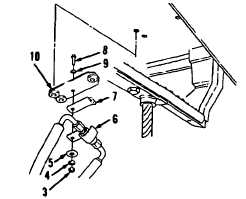
2.
Remove nut (3), washers (4 and 5), clip (6),
bracket (7), bolt (8), washer (9) and plate
(10, Figure 11-47).
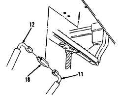
NOTE
All hose and tube assemblies must
be tagged before disconnecting to
aid in installation. Cap all hose and
tube ends and plug all open hydraulic
ports to prevent contamination.
3.
Disconnect hose assemblies (11 and 12)
holding body (18, Figure 11-48).
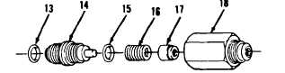
DISASSEMBLY
1.
Remove seal (13), adapter (14) and seal
(15, Figure 11-49). Discard seals (13 and
15).
2.
Remove spring (16) and check (17) from
body (18).
CLEANING
Clean all parts. Refer to Chapter 2.
Figure 11-49
Figure 11-46
Figure 11-47
Go to Sheet 3
Figure 11-48
11-33