POWER TRAIN
TM 5-3805-263-14&P-2
DISASSEMBLY AND ASSEMBLY
TRANSMISSION GEARS
21. Do Steps 1 through 20 for the other clutch.
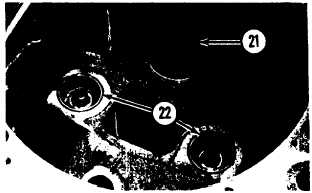
22. Lower the temperature of the three bearing
cups. Install bearing cup (21) for the input
gear shaft. Install bearing cups (22) for the
two directional clutches.
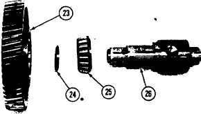
23. Lower the temperature of the two bearing
cups for idler gear (23). Install the lock ring
and the two bearing cups in the gear.
24. Install bearing (25) and spacer (24) on shaft
(26). Install the idler gear on the shaft.
25. Tilt the gear on the shaft and install the
shaft and gear in the case as a unit.
26. Install a 3/4”-10 NC forged eyebolt in the
directional clutch. Fasten a hoist to the
eyebolt.
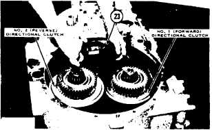
27. Lift idler gear (23). Install the directional
clutch in the case. Remove the hoist and
eyebolt.
28. Do Steps 26 and 27 for the other direc-
tional clutch. Install the other bearing for
the idler gear.
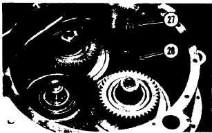
29. Heat bearings (27) for the input gear shaft
in oil to a temperature of 275° F (135° C).
Install the bearings on the shaft.
30. Install input gear (28) in the case.
2-114