
TM 5-3805-293-23-5
0310
INSTALLATION CONTINUED
000310
Right Blade Lift Cylinder Lines
000310
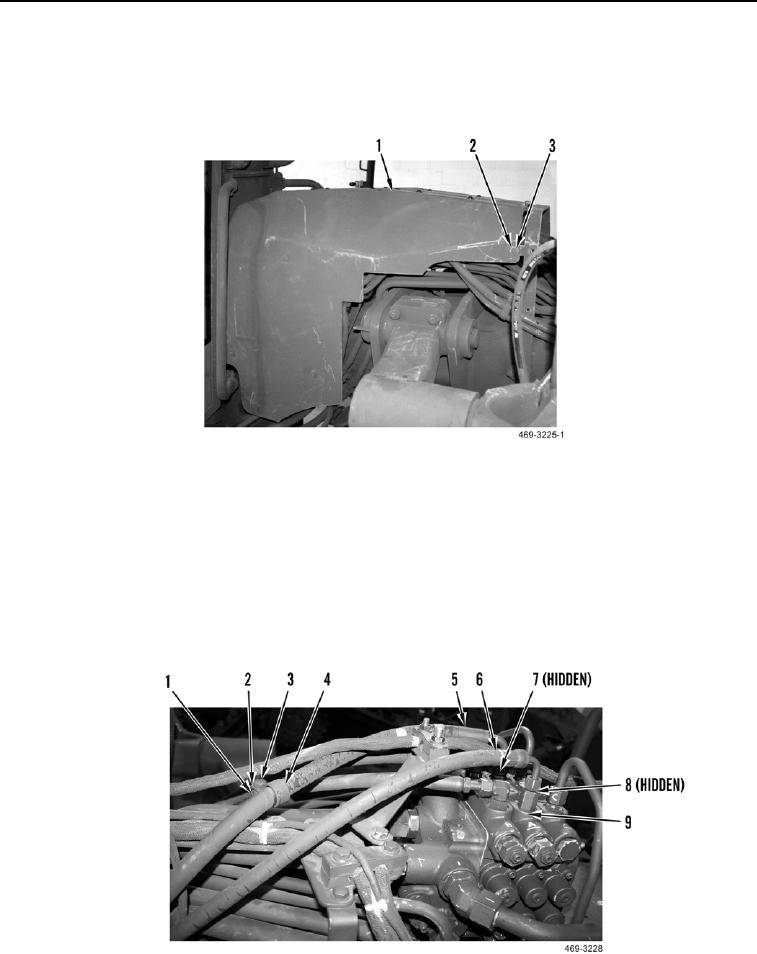
12. Install rearward front frame cover (Figure 15, Item 1), 10 washers (Figure 15, Item 2), and bolts (Figure 15,
Item 3) on machine.
Figure 15. Rearward Front Frame Cover.
0310
END OF TASK
Left Blade Lift Cylinder Lines
000310
1. Install new O-ring (Figure 16, Item 8) and connect hose (Figure 16, Item 6) to rear valve (Figure 16, Item 9).
2. Install new O-ring (Figure 16, Item 7) and connect hose (Figure 16, Item 5) to rear valve (Figure 16, Item 9).
3. Install clamp (Figure 16, Item 4), washer (Figure 16, Item 2), and bolt (Figure 16, Item 3) on hose (Figure 16,
Item 5) and stanchion (Figure 16, Item 1).
Figure 16. Left Rear Valve.
0310