
TM 5-3805-293-23-5
0302
REMOVAL CONTINUED
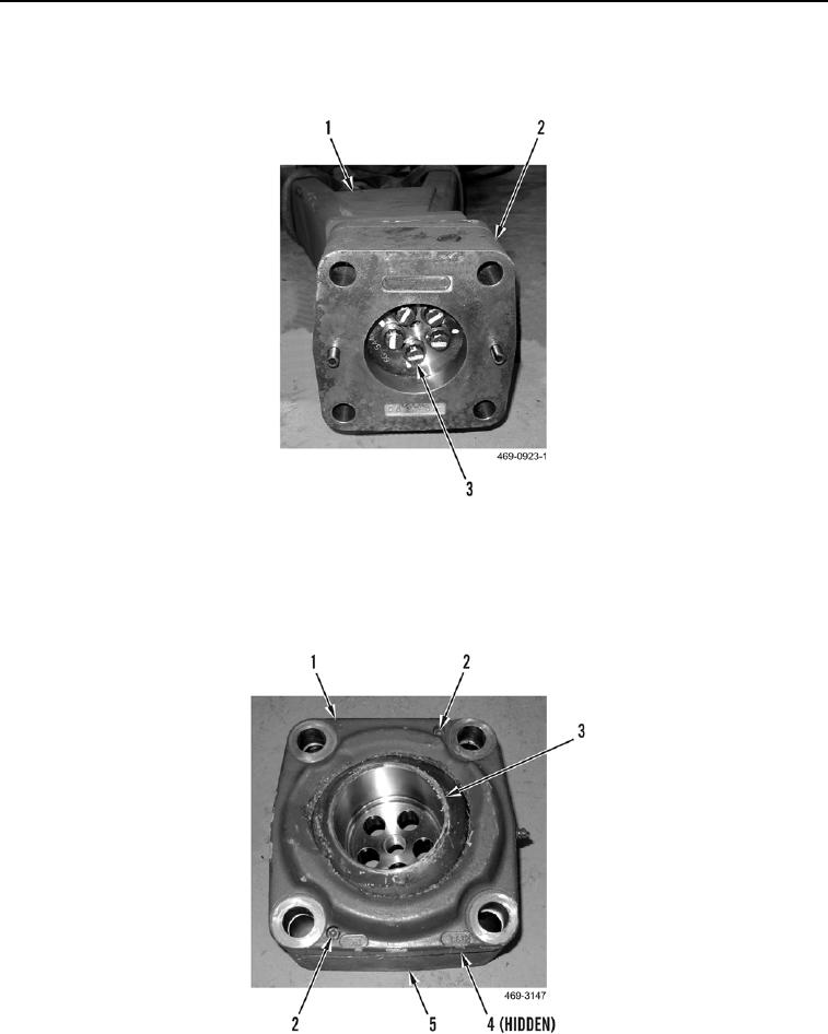
50. Remove five bolts (Figure 23, Item 3) and adapter assembly (Figure 23, Item 2) from drawbar and yoke (Figure
23, Item 1)
.
Figure 23. Drawbar and Yoke Adapter Assembly.
0302
N OT E
Note the number of shims to aid in installation.
51. Remove two hex screws (Figure 24, Item 2), coupler (Figure 24, Item 1), shims (Figure 24, Item 4), and ball
(Figure 24, Item 3) from adapter assembly (Figure 24, Item 5).
Figure 24. Adapter Assembly.
0302
END OF TASK