
TM 5-3805-293-23-5
0283
ASSEMBLY CONTINUED
4. Install slide lock frame (Figure 24, Item 1), two washers (Figure 24, Item 3), and bolts (Figure 24, Item 2) on
joystick support (Figure 24, Item 4).
Figure 24. Slide Lock Frame.
0283
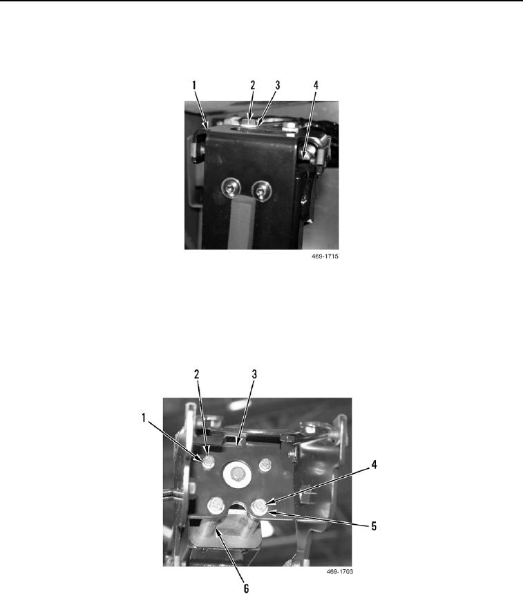
5. Install joystick control bracket (Figure 25, Item 3), two washers (Figure 25, Item 5), and bolts (Figure 25,
Item 4), on support slide lock frame (Figure 25, Item 6).
6. Install two washers (Figure 25, Item 1) and bolts (Figure 25, Item 2) on joystick control bracket (Figure 25,
Item 3).
Figure 25. Joystick Control Bracket.
0283