
TM 5-3805-293-23-4
0265
INSTALLATION CONTINUED
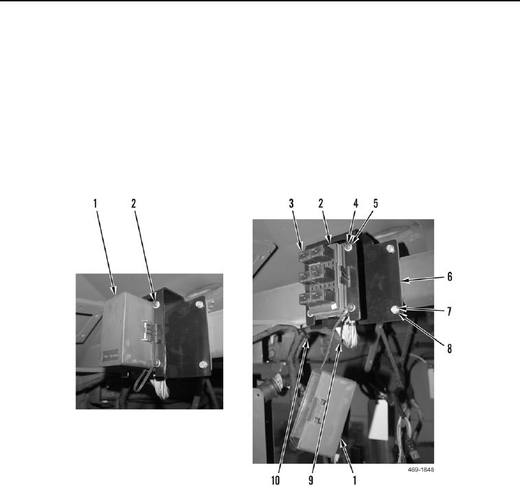
7. Install bracket (Figure 12, Item 6), washers (Figure 12, Item 8) and four bolts (Figure 12, Item 7) on cab.
8. Install cab upper wiring harness (Figure 12, Item 9) and new tiedown strap (Figure 12, Item 10) on cab.
9. Install relay panel (Figure 12, Item 2), cover (Figure 12, Item 1), four washers (Figure 12, Item 5), and screws
(Figure 12, Item 4) on bracket (Figure 12, Item 6).
N OT E
Install relays as marked during removal.
10. Install six relays (Figure 12, Item 3) on relay panel (Figure 12, Item 2).
11. Install cover (Figure 12, Item 1) on relay panel (Figure 12, Item 2).
Figure 12. Relay Panel Connections.
0265

