
TM 5-3805-293-23-4
0251
REMOVAL CONTINUED
000251
N OT E
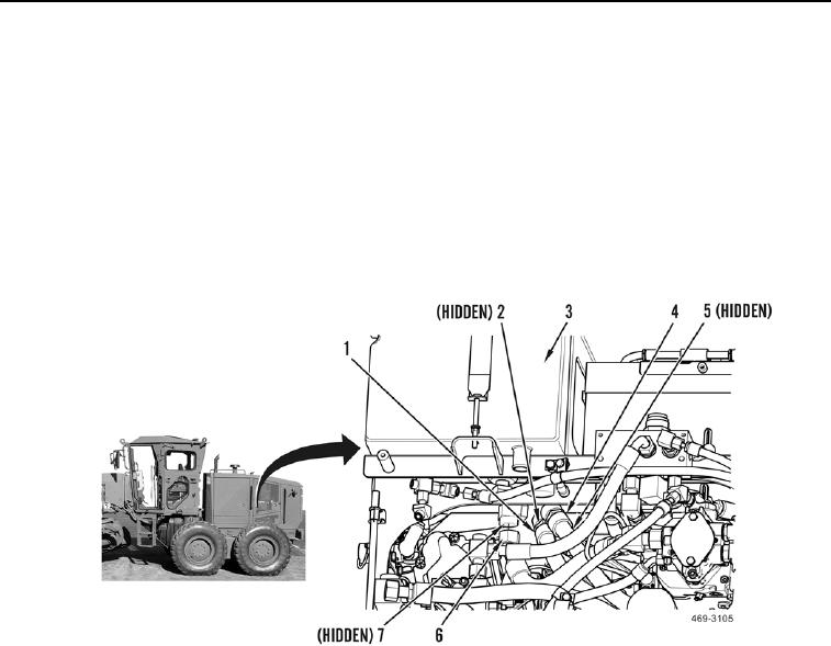
Hydraulic service pack bracket is shown partially removed for clarity.
3. Disconnect hose (Figure 3, Item 4) and remove O-ring (Figure 3, Item 5) from hydraulic tank (Figure 3, Item 3).
Discard O-ring.
4. Disconnect hose (Figure 3, Item 6) and remove O-ring (Figure 3, Item 7) from hydraulic tank (Figure 3, Item 3).
Discard O-ring.
5. Disconnect hose (Figure 3, Item 1) and remove O-ring (Figure 3, Item 2) from hydraulic tank (Figure 3, Item 3).
Discard O-ring.
6. Remove hose (Figure 3, Item 1) from machine.
Figure 3. AWD Bypass Valve Hose at Hydraulic Tank.
0251
END OF TASK
CLEANING AND INSPECTION
000251
Clean and inspect all parts IAW Mechanical General Maintenance Instructions (WP 0346).
END OF TASK
INSTALLATION
000251
N OT E
Install all hoses as marked and tagged during removal.
Hydraulic service pack bracket isshown partially removed for clarity.
1. Route hose (Figure 3, Item 1) on machine.
2. Install new O-ring (Figure 3, Item 2) and connect hose (Figure 3, Item 1) to hydraulic tank (Figure 3, Item 3).
3. Install new O-ring (Figure 3, Item 7) and connect hose (Figure 3, Item 6) to hydraulic tank (Figure 3, Item 3).
4. Install new O-ring (Figure 3, Item 5) and connect hose (Figure 3, Item 4) to hydraulic tank (Figure 3, Item 3).

