
TM 5-3805-293-23-4
0242
REMOVAL CONTINUED
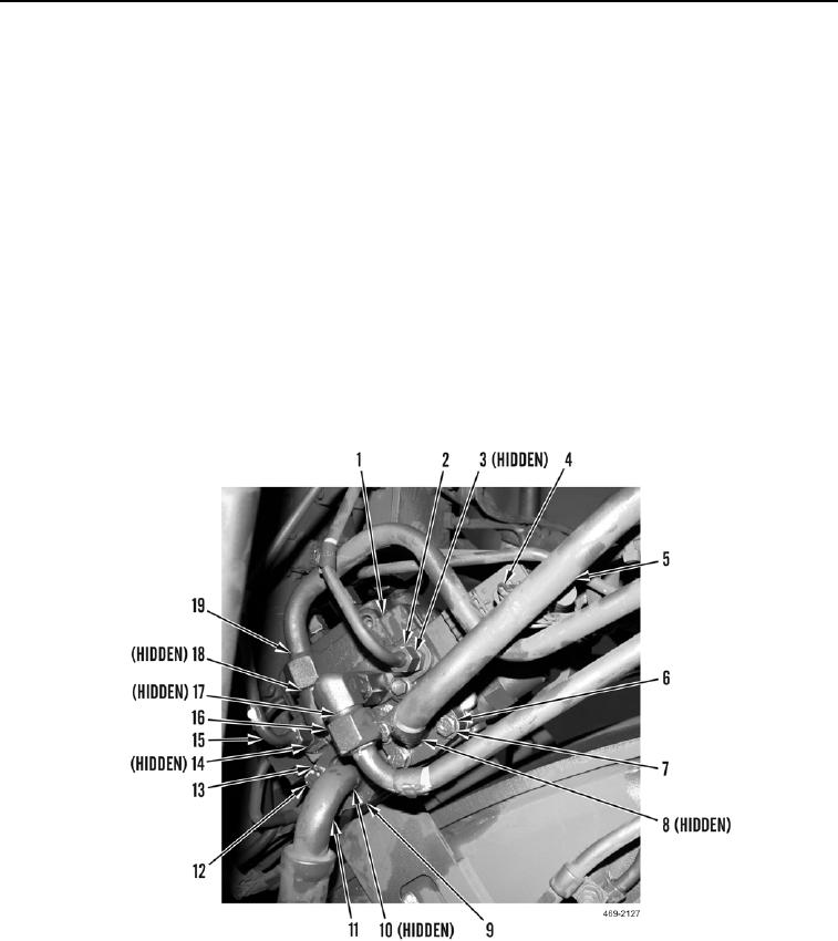
3. Disconnect front attachment wiring harness connector (Figure 3, Item 4) from steering control valve (Figure 3,
Item 1).
4. Remove four bolts (Figure 3, Item 7), washers (Figure 3, Item 6), pressure supply tube assembly (Figure 3,
Item 5) and O-ring (Figure 3, Item 8) from steering control valve (Figure 3, Item 1). Discard O-ring.
5. Remove four bolts (Figure 3, Item 12), washers (Figure 3, Item 13), and split flange (Figure 3, Item 9) from
steering control valve (Figure 3, Item 1).
6. Remove pressure supply hose (Figure 3, Item 11) and O-ring (Figure 3, Item 10) from steering control valve
(Figure 3, Item 1). Discard O-ring.
7. Remove tube (Figure 3, Item 15) and O-ring (Figure 3, Item 14) from steering control valve (Figure 3, Item 1).
Discard O-ring.
8. Remove tube (Figure 3, Item 2) and O-ring (Figure 3, Item 3) from steering control valve (Figure 3, Item 1).
Discard O-ring.
9. Remove tube (Figure 3, Item 16) and O-ring (Figure 3, Item 17) from steering control valve (Figure 3, Item 1).
Discard O-ring.
10. Remove tube (Figure 3, Item 19) and O-ring (Figure 3, Item 18) from steering control valve (Figure 3, Item 1).
Discard O-ring.
Figure 3. Steering Control Valve Side Tube.
0242

