
TM 5-3805-293-23-4
0218
REAR VALVE BANK CONTINUED
Blade Lift Circuit (Engine Non-Operational)
1. Left Side.
a. Shut off machine (TM 5-3805-293-10).
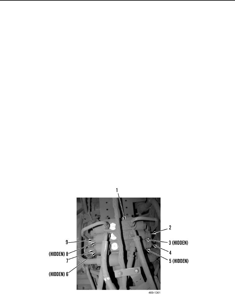
b. Slowly turn left blade lift lock valve (Figure 19, Item 9) and left blade lift relief valve (Figure 19, Item 2) three
complete turns. Allow pressure to release.
c.
Remove left blade lift lock valve (Figure 19, Item 9) and O-rings (Figure 19, Item 8) from manifold
(Figure 19, Item 1). Discard O-rings.
d. Remove left blade lift relief valve (Figure 19, Item 2) and O-rings (Figure 19, Item 3) from manifold
(Figure 19, Item 1). Discard O-rings.
e. Install new O-rings (Figure 19, Item 3) on left blade lift relief valve (Figure 19, Item 2). Install left blade lift
relief valve on manifold (Figure 19, Item 1).
f.
Install new O-rings (Figure 19, Item 8) on left blade lift lock valve (Figure 19, Item 9). Install left blade lift
lock valve on manifold (Figure 19, Item 1). Torque to 59 11 lb-ft (80 15 Nm).
2. Right Side.
a. Shut off machine (TM 5-3805-293-10).
b. Slowly turn right blade lift lock valve (Figure 19, Item 7) and right blade lift relief valve (Figure 19, Item 4)
three complete turns. Allow pressure to release.
c.
Remove right blade lift lock valve (Figure 19, Item 7) and O-rings (Figure 19, Item 6) from manifold
(Figure 19, Item 1). Discard O-rings.
d. Remove right blade lift relief valve (Figure 19, Item 4) and O-rings (Figure 19, Item 5) from manifold
(Figure 19, Item 1). Discard O-rings.
e. Install new O-rings (Figure 19, Item 5) on right blade lift relief valve (Figure 19, Item 4). Install right blade lift
relief valve on manifold (Figure 19, Item 1).
f.
Install new O-rings (Figure 19, Item 6) on right blade lift lock valve (Figure 19, Item 7). Install right blade lift
lock valve on manifold (Figure 19, Item 1). Torque to 59 11 lb-ft (80 15 Nm).
Figure 19. Blade Lift Circuit.
0218
END OF TASK
Change 1

