
TM 5-3805-293-23-4
0202
INSTALLATION CONTINUED
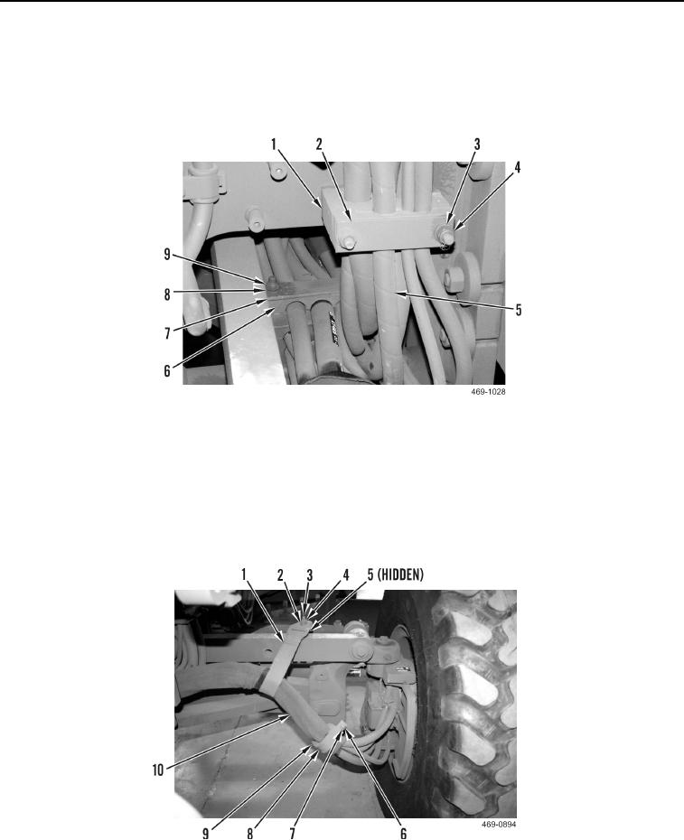
9. Install inserts (Figure 28, Item 1), plate (Figure 28, Item 2), washers (Figure 28, Item 3), and two new locknuts
(Figure 28, Item 4) on hose bundle (Figure 28, Item 5).
10. Install inserts (Figure 28, Item 6), plate (Figure 28, Item 7), washers (Figure 28, Item 8), and two new locknuts
(Figure 28, Item 9) on hose bundle (Figure 28, Item 5).
Figure 28. Hose Bundle.
0202
11. Install rubber insulator (Figure 29, Item 9) and two-piece clamp (Figure 29, Item 8) on hose bundle (Figure 29,
Item 10).
12. Install washer (Figure 29, Item 7) and bolt (Figure 29, Item 6) on two-piece clamp (Figure 29, Item 8).
13. Install spacer (Figure 29, Item 5), holding strap (Figure 29, Item 1), washer (Figure 29, Item 2), and new lock-
nut (Figure 29, Item 4) on stud (Figure 29, Item 3).
Figure 29. Left Holding Strap.
0202
Change 1

