
TM 5-3805-293-23-4
0188
REMOVAL CONTINUED
N OT E
Tag and mark wires and connectors to aid in installation.
Note routing of rear chassis wiring harness to aid in installation.
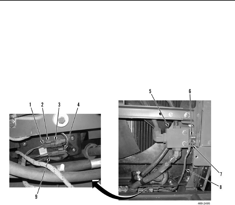
3. Remove tiedown strap (Figure 2, Item 7) from rear chassis wiring harness (Figure 2, Item 8). Discard tiedown
strap.
4. Disconnect rear chassis wiring harness connector (Figure 2, Item 6) from fan control (Figure 2, Item 5).
5. Disconnect rear chassis wiring harness connector (Figure 2, Item 9) from backup alarm (Figure 2, Item 4).
6. Disconnect rear chassis wiring harness connector (Figure 2, Item 1) from fan solenoid control harness
connector (Figure 2, Item 3) and remove from clip (Figure 2, Item 2).
Figure 2. Fan and Backup Alarm Connections.
0188
Change 1

