
TM 5-3805-293-23-3
0161
INSTALLATION
000161
1. Install sling and lifting device on wheel lean arm.
WARN I N G
Use extreme caution when handling heavy parts. Provide adequate support and use
assistance during procedure. Ensure any lifting device used is in good condition and of
suitable load capacity. Keep clear of heavy parts supported only by lifting device. Failure
to follow this warning may cause injury or death to personnel.
N OT E
Wheel lean arm weighs approximately 500 lb (226 kg).
2. Using lifting device, install wheel lean arm on machine.
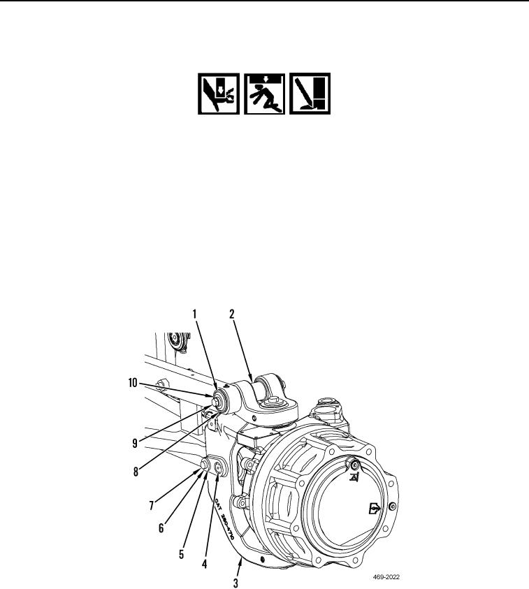
3. Install pin (Figure 3, Item 4), spacer (Figure 3, Item 5), washer (Figure 3, Item 6), and bolt (Figure 3, Item 7) on
wheel lean arm (Figure 3, Item 3). Torque to 148 lb-ft (658 Nm).
4. Install spacer (Figure 3, Item 2), pin (Figure 3, Item 8), retainer (Figure 3, Item 1), washer (Figure 3, Item 10),
and bolt (Figure 3, Item 9) on wheel lean arm (Figure 3, Item 3). Torque to 148 lb-ft (658 Nm).
Figure 3. Wheel Lean Arm.
0161
5. Remove lifting device and sling from wheel lean arm.