
TM 5-3805-293-23-3
0141
REMOVAL CONTINUED
N OT E
The procedure for axle link removal and replacement is identical for left and right axle
links. Right axle link is shown in this procedure.
8. Position lifting device under axle link.
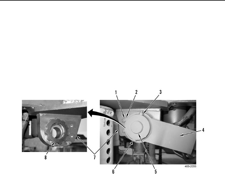
9. Remove two bolts (Figure 3, Item 2), washers (Figure 3, Item 1) and plate (Figure 3, Item 7) from machine.
10. Remove two nuts (Figure 3, Item 3), bolts (Figure 3, Item 6), and pin (Figure 3, Item 5) from axle link (Figure 3,
Item 4).
11. Remove axle link (Figure 3, Item 4) from machine.
12. Remove cam (Figure 3, Item 8) from machine.
Figure 3. Axle Link.
0141