
TM 5-3805-293-23-3
0130
INSTALLATION CONTINUED
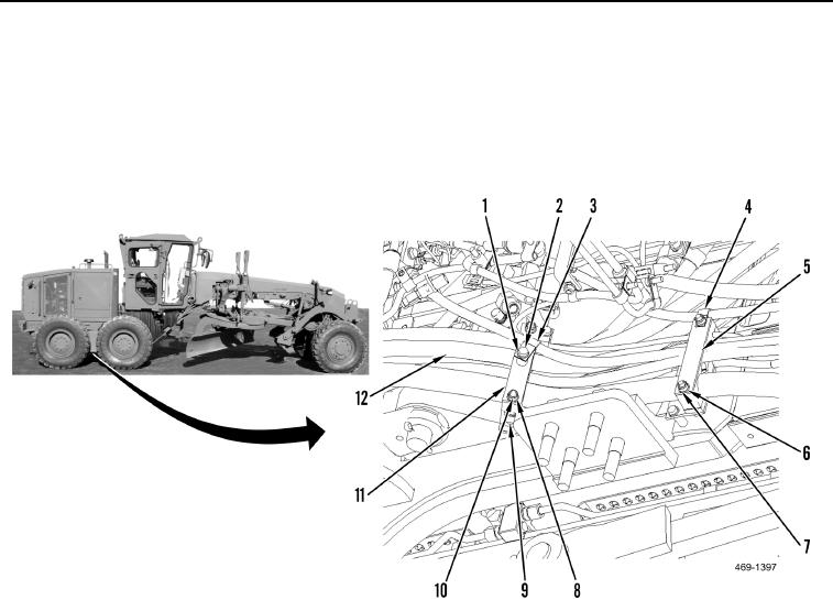
37. Install plate (Figure 35, Item 5), clamp (Figure 35, Item 4), two washers (Figure 35, Item 6), and nuts
(Figure 35, Item 7) on hose bundle (Figure 35, Item 12).
38. Install block (Figure 35, Item 9), and position plate (Figure 35, Item 11) on hose bundle (Figure 35, Item 12).
39. Install two washers (Figure 35, Item 10), nuts (Figure 35, Item 8), clamp (Figure 35, Item 3), washer (Figure 35,
Item 2), and bolt (Figure 35, Item 1) on hose bundle (Figure 35, Item 12).
Figure 35. Hose Plate and Blocks.
0130