
TM 5-3805-293-23-3
0130
REMOVAL CONTINUED
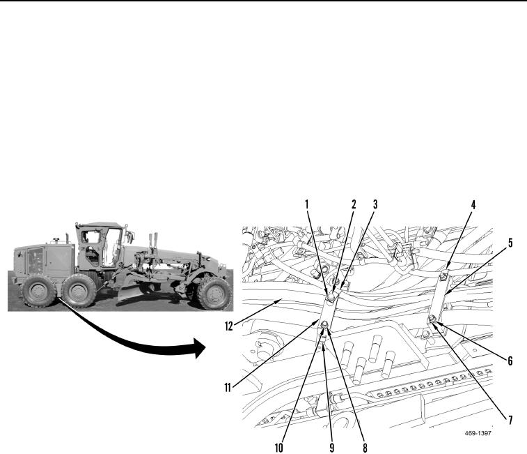
7. Remove bolt (Figure 7, Item 1), washer (Figure 7, Item 2), clamp (Figure 7, Item 3), two nuts (Figure 7, Item 8),
and washers (Figure 7, Item 10) from hose bundle (Figure 7, Item 12).
8. Position plate (Figure 7, Item 11) aside, and remove block (Figure 7, Item 9) from hose bundle (Figure 7,
Item 12).
9. Remove two nuts (Figure 7, Item 7), washers (Figure 7, Item 6), clamp (Figure 7, Item 4), plate (Figure 7,
Item 5) from hose bundle (Figure 7, Item 12).
N OT E
Rear axle removed for clarity.
Figure 7. Hose Plate Blocks.
0130