
TM 5-3805-293-23-3
0067
INSTALLATION CONTINUED
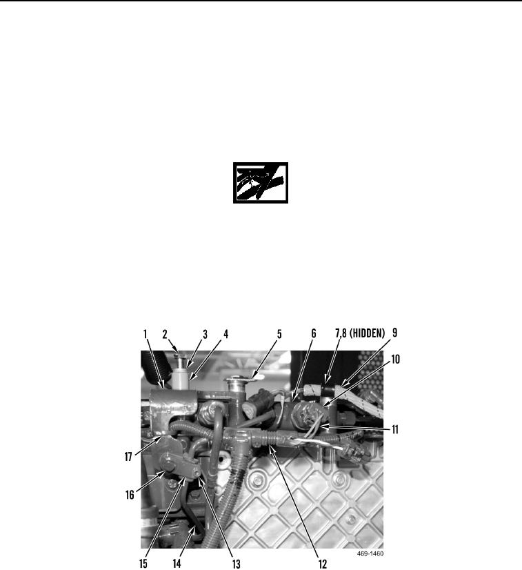
9. Install fuel rail bracket (Figure 14, Item 1), two spacers (Figure 14, Item 4), clips (Figure 14, Item 5), washers
(Figure 14, Item 3), and bolts (Figure 14, Item 2) on fuel rail (Figure 14, Item 6).
10. Install spacer (Figure 14, Item 10), wiring harness clip (Figure 14, Item 9), washer (Figure 14, Item 8) and bolt
(Figure 14, Item 2) to fuel rail (Figure 14, Item 6).
11. Tighten two ECM mounting bracket bolts.
12. Connect engine control harness (Figure 14, Item 12) to fuel pressure sensor (Figure 14, Item 11).
13. Install new tiedown strap (Figure 14, Item 17) on engine control harness (Figure 14, Item 12).
WARN I N G
Do not bend high-pressure fuel line to gain access for ECM mounting bracket installation.
The fuel system operates under extremely high pressure. Bending, loosening, or
retightening high-pressure fuel lines renders them weaker and prone to failure. Replace
any high-pressure fuel line that has been bent, loosened, and/or retightened. Failure to
follow this warning may result in injury or death to personnel.
14. Install clip (Figure 14, Item 15), allen screw (Figure 14, Item 13), and bolt (Figure 14, Item 16) on high-pressure
fuel supply line (Figure 14, Item 14).
Figure 14. Fuel Rail Bracket.
0067