
TM 5-3805-293-10
0004
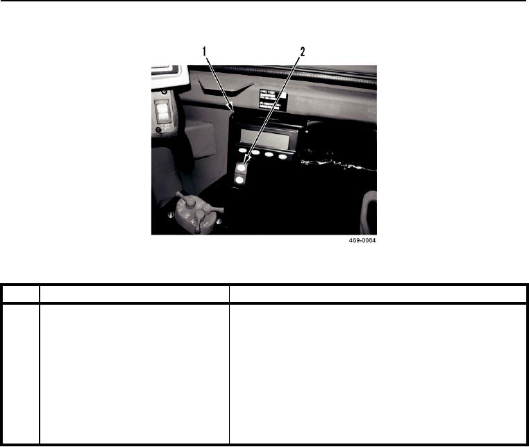
MESSENGER DISPLAY AND IMPLEMENT LOCKOUT SWITCH
0004
Figure 20. Messenger Display and Implement Lockout Switch.
0004
KEY
COMPONENT
DESCRIPTION
1
Messenger Display
Provides machine information through various menus
(Performance Menu, Totals Menu, Settings Menu, Service
Menu), includes a self-diagnostic function test and four distinct
warning categories to alert the operator of a situation requiring
attention.
2
Implement Lockout Switch
Push top of switch to lock out implement controls. Push
bottom of switch to unlock implement controls. Implements
must be locked out during transport or while loading to prevent
inadvertent movement.
Note: Steering is not affected by position of switch.
0004-22