ENGINE
TURBOCHARGER
DISASSEMBLY AND ASSEMBLY
TM 5-3805-263-14&P-2
7.
8.
9.
10.
11.
12.
13.
14.
15.
16.
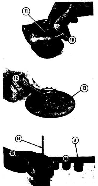
Put bearing (10) and the collar in position on
the cartridge housing as a unit. Make an align-
ment of the holes in the bearing with dowels
(11).
Put spring (12) in position in backplate (13).
Put shaft assembly (14) in position on tooling
(A).
Fill the groove in the shaft with 6V2055 High
Vacuum Grease.
Put seal ring (16) in position on the shaft as-
sembly.
Install shroud (15) as shown.
Put the cartridge housing in position on shaft
assembly ( 14).
Install the backplate, locks (18) and bolts (17).
Tighten the bolts to a torque of 75-90 lb.in.
(8.5-10.2 N•m).
Bend the tabs on locks (18) up against the bolts.
Put compressor wheel (19) in position and in-
stall the nut.
CAUTION
Do not put a bending force on the shaft and
wheel assembly when the nut is tightened.
17. Tighten the nut to a torque of 20 lb.in. (2.3
N•m) plus 100°.
1-97


