TM 5-3805-263-14&P-3
ELECTRICAL TROUBLESHOOTING
INDIVIDUAL CIRCUIT DESCRIPTION
BLADE FLOAT
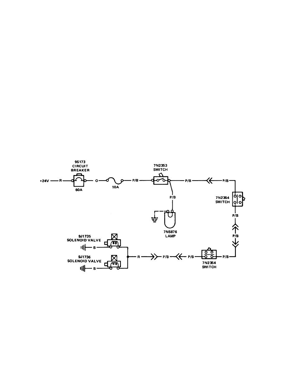
The blade float circuit is made up of two solenoid valves (a N.O. 9J1736 and N.C. 9J1735), an ON/OFF
7N2353 Toggle Switch,--two 7N2354 Limit Switches, and a 7N5876 Indicator Lamp. The limit switches
are connected to the linkage of the left and right blade lift controls.
When the ON/OFF switch is turned ON, the solenoid valves are activated and they send the hydraulic flow
so that the blade follows the level of the ground. The indicator lamp is also turned ON. If there is a
sudden need to adjust the position of the blade, it is not necessary to turn OFF the ON/OFF switch. When
either blade control lever is moved, the limit switch, connected to its linkage, opens and turns OFF the
float control circuit. The movement of the blade control lever will deactivate the float control circuit and
change the position of the blade.
Power for the circuit is from the 60 amp main circuit breaker through a 10 amp fuse for the blade float
circuit.
Figure 19. Blade Float Circuit
4-58


