ELECTRICAL TROUBLESHOOTING
TM 5-3805-263-14&P-3
EMS PANEL
OPERATOR PANEL
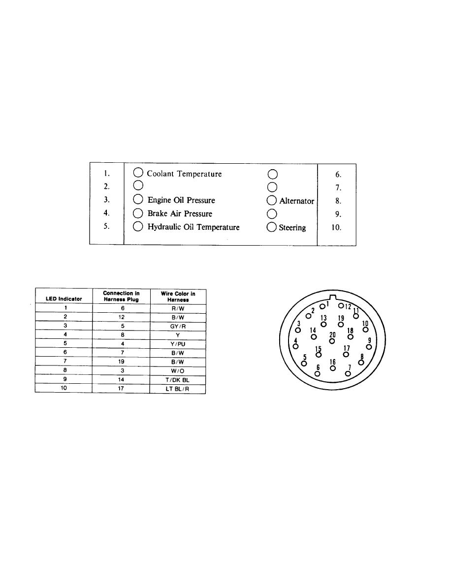
The Operator Panel has ten light emitting diode (LED) indicators. However, only
six of these are used. Each indicator is turned on by the internal circuits of the
operator panel when its control wire is open (not continuous to ground). The
indicators that are used have temperature or pressure switches that open or close
their control circuits. Because an indicator turns ON when its control circuit is open,
the unused indicators on the operation panel must have their control wire grounded
so they are turned OFF, continuously. The following table shows the contacts in the
connector that goes to the operator panel and the wire colors in the harness, that are
the control wires for all of the indicators on the operator panel.
The control wires for indicators 2, 6, 7 and 10 are spliced (fastened) together in the
first 11.8 in. (300 mm) of the harness and connected to ground. If an unused
indicator turns ON, it could be an indication of a control wire that is broken and
therefore, not grounded.
4-44


