TM 5-3805-263-14&P-3
BLADE CIRCLE DRIVE
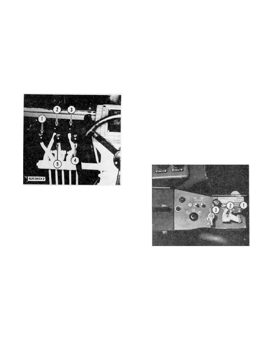
CONTROL GROUPS
Push the lever (4) forward to rotate the circle
CENTERSHIFT
counterclockwise.
HOLD - The circle will not move.
Push the lever (2) forward to move the circle to the
Pull the lever (4) to the back to rotate the circle
left.
clockwise.
HOLD - The circle will not move.
BLADE SIDESHIFT
Push the lever (5) forward to move the blade to the
Pull the lever (2) back to move the circle to the right.
left.
HOLD - The blade will not move.
When operating, the centershift lock pin control
Pull the lever (5) back to move the blade to the
must be in LOCK position.
right.
ARTICULATION
WHEEL LEAN
Push the lever (3) forward to lean the front wheels
to the left.
HOLD - The wheels will not move.
Pull the lever (3) back to lean the front wheels to the
right.
BLADE LIFT (RIGHT SIDE)
Push the lever (4) forward to lower the right side of
the blade.
HOLD - The blade will not move.
Pull the lever (4) back to raise the right side of the
blade.
CENTERSHIFT LOCK PIN
HYDRAULIC CONTROLS
1. Articulation. 2. Centershift. 3. Wheel lean.
4.
Blade lift (right side).
Push the lever ( I ) forward to move the rear of the
machine to the left.
HOLD - The machine will not move.
Pull the lever (I) back to move the rear of the
machine to the right.
CENTERSHIFT LOCK PIN
1. RETRACTS pin from centershift hole. 2. INDEX -
Tension is applied to locate the pin in the hole. 3. LOCK
- Pin is moved fully in the hole.
4-8


