TM 5-3805-261-34
BRAKES MAINTENANCE.
6-11.
Air Brake Reservoir Lines and Fittings. (Sheet 2 of 3)
REMOVAL
NOTE
All hose and tube assemblies must be
tagged before disconnecting to aid in
installation. Cap all hose and tube ends
to prevent contamination.
1.
Disconnect air brake reservoir.
Refer to paragraph 6-10, steps 1,
2 and 3.
2.
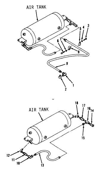
Disconnect hose assembly (9,
Figure 6-28) from air compressor.
3.
Remove elbows (1 and 2).
4.
Remove bolt (3), washer (4), clip
(5), bolt (6), washer (7) and
clip (8).
5.
Remove hose assembly (9) from air
tank.
6.
Disconnect hose assembly (13,
Figure 6-29).
7.
Remove elbow (10), valve (11) and
elbow (12) from air tank.
8.
Remove hose assembly (13),
connector (14), bushing (15), tee
(16). valve (17) and elbow (18).
CLEANING
Clean all parts. Refer to Chapter 2.
INSPECTION
Inspect all parts. Refer to Chapter
2.
Go to Sheet 3
6-45
Figure 6-28.
Figure 6-29.

