TM 5-3805-261-23-1
DIMMER SWITCH REPLACEMENT - CONTINUED
0103 00
REMOVAL - CONTINUED
NOTE
Tag wire assemblies before disconnecting to aid in installation.
2.
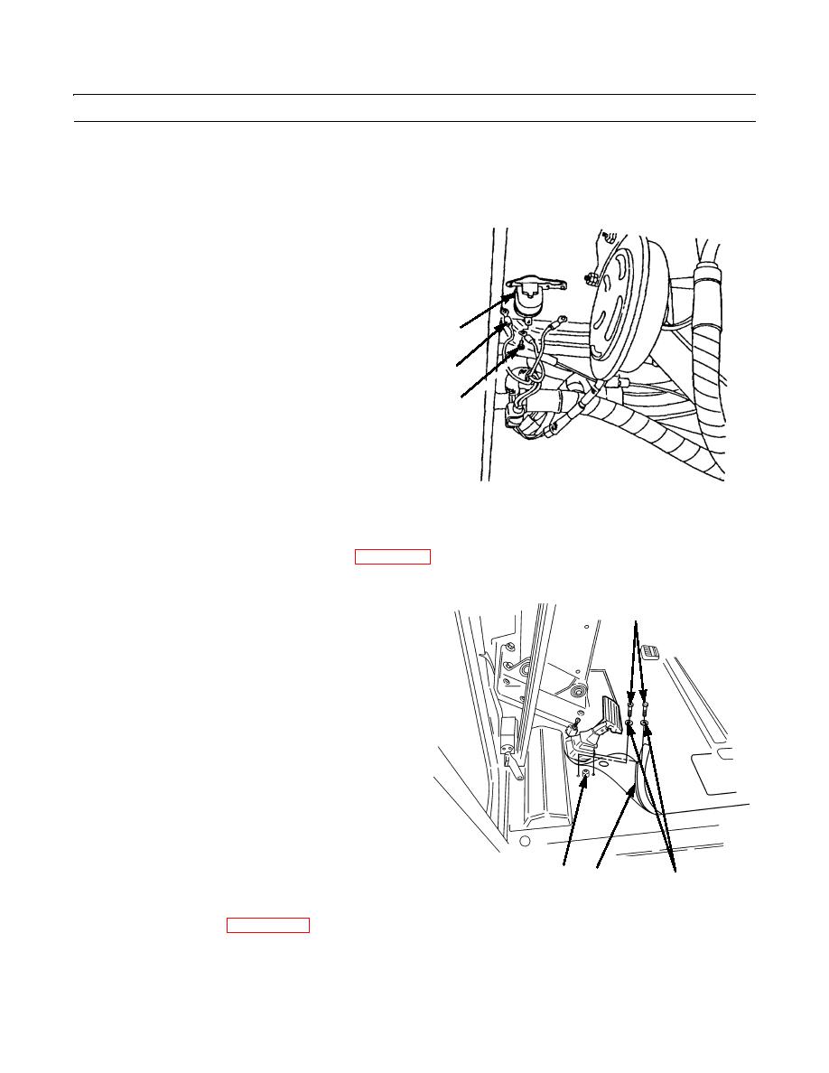
Under left side of cab floor, remove three screws (5)
and disconnect three wire assemblies (6) from switch
(4).
4
6
5
397-306
CLEANING AND INSPECTION
Clean and inspect all parts in accordance with WP 0021 00.
INSTALLATION
1
1.
Under left side of cab floor, connect three wire assem-
blies (6) and install three screws (5) to switch (4).
2.
Install switch (4), two washers (2), and screws (1).
3.
Lay down corner of floor mat (3).
397-305
3
4
2
4.
Connect battery cables (WP 0125 00).
END OF WORK PACKAGE
0103 00-2


