TM 5-3805-261-20
PRINCIPLES OF OPERATION.
1-30.
GAGES AND INDICATORS (NON-ELECTRICAL).
a.
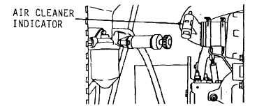
Air Cleaner Indicator (Figure 1-55). Mounted on air inlet elbow. Contains a vacuum sensitive, color coded
piston inside of a calibrated plastic housing. When air cleaner elements become dirty, air inlet vacuum increases and
moves the piston so that red appears in an aperture on the housing. This indicates that the elements need cleaning or
replacing. After cleaning or replacing, indicator is reset and green appears at the aperture.
Figure 1-55.
b.
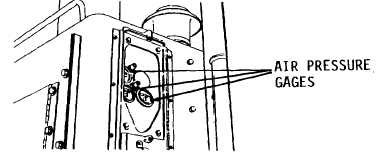
Air Pressure Gages (Figure 1-56). Mounted in instrument panel at forward section of engine hood. Each
one is connected by air lines to a section of the dual air tank. Each shows air pressure for one section of the air tank.
Figure 1-56.
c.
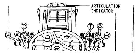
Articulation Indicator (Figure 1-57). Mounted behind steering console. Connected by lever and cable
downward through cab floor and linked to rear frame. Registers amount of articulation (pivoting) of frame from straight (0)
to maximum (FULL).
Figure 1-57.
1-49


