TM 5-3805-261-20
PRINCIPLES OF OPERATION.
1-29.
HYDRAULIC SYSTEM.
d.
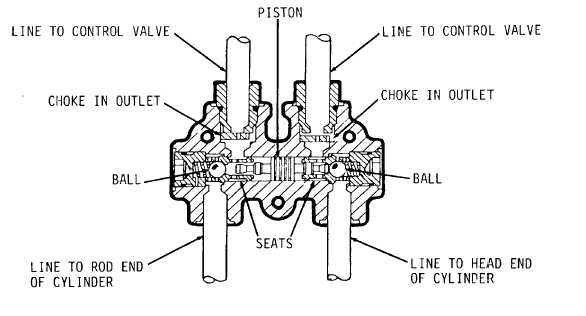
Lock Check Valve (Figure 1-48). There is a lock check valve between the control valve and the hydraulic
cylinder (of motor) in each of the hydraulic systems. The purpose of each lock check valve is the same, but several
designs are used because of the different systems requirements. Lock check valves prevent hydraulic cylinder rods from
drifting when the controls are in HOLD (neutral) position by locking the hydraulic pressure in against ball check valves.
Outlet chokes in lock check valves serve to slow down the hydraulic flow when needed. Relief valves serve to prevent
overloading the system.
The circle drive and leaning wheel systems use lock check valves without chokes or relief valves.
The centershift, articulation, and right hand lift systems use lock check valves with chokes and without relief valves.
The left hand lift system and the scarifier system use lock check valves with chokes and a relief valve.
The tip and sideshift systems use lock check valves with relief valves but without chokes.
When the control valve is in HOLD position, the oil in lines is stopped and the rod in the cylinder cannot move. The
springs against balls, and the oil in lines, keep the balls on seats. The oil in lines is at tank pressure.
Figure 1-48.
1-45