
TM 5-3805-261-23-2
SCHEMATIC DIAGRAMS - CONTINUED
0352 00
1
2
3
6
4
5
7
8
13
12
9
11
10
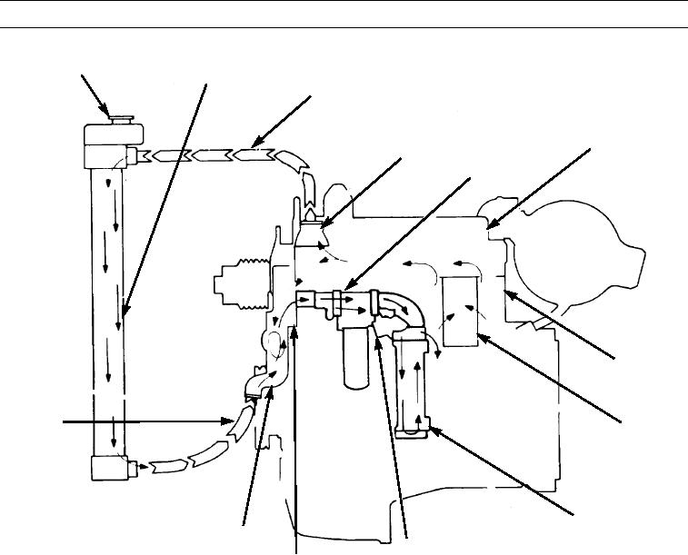
LEGEND
8.
Inlet line for water pump
1.
Filler cap
9.
Water pump
2.
Radiator
10.
Internal bypass
3.
Inlet line for radiator
11.
Bonnet
4.
Water temperature regulator
12.
Transmission oil cooler
5.
Engine oil cooler
13.
Cylinder liner
6.
Cylinder head
7.
Cylinder block
397-901
Figure 12. Cooling System Schematic.
0352 00-33