TM 5-3805-261-23-1
SCHEMATIC DIAGRAMS - CONTINUED
0352 00
1
2
3
5
4
13
6
7
8
12
9
13
11
13
10
14
15
16
397-898
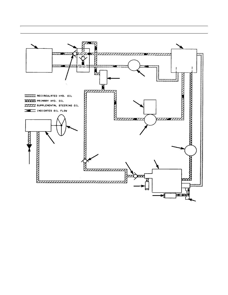
LEGEND
9.
Metering valve for steering
1.
Cooler for hydraulic oil
10.
Flow to relief valves and steering cylinder
2.
By-pass valve for oil cooler
11.
Combination valve
3.
Hydraulic tank
12.
Implement pump
4.
Relief valve (supplemental steering)
13.
Check valves
5.
Pump for oil to oil cooler
14.
Pressure sensing switch
6.
Electric motor
15.
Dump valve switch
7.
Steering wheel
16.
Dump valve
8.
Supplemental steering pump
Figure 9. Supplemental Steering Hydraulic Schematic (Non-actuated).
0352 00-29


