TM 5-3805-261-23-1
SCARIFIER ASSEMBLY REPLACEMENT - CONTINUED
0264 00
INSTALLATION - CONTINUED
NOTE
1
Tighten bolts hand-tight only.
17.
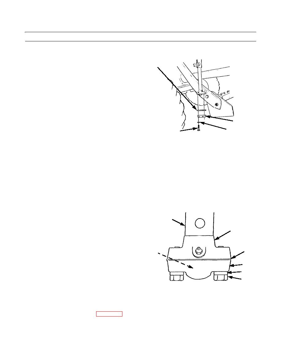
Install spacer (s) (1), cap (2), two washers (3), and
bolts (4).
2
4
3
397-2192
CAUTION
For proper final assembly, ball inside cap must have free play (clearance) of 0.015 to 0.045 in. (0.38 to 1.14
mm) after bolts are fully tightened. Failure to obtain the correct clearance could cause damage to machine.
NOTE
Do not overtighten bolts.
18.
Tighten two bolts (4) evenly only until there is no free play (clearance) between ball (5) and cap (2).
19.
Examine cap (2), socket (6) of rod (8), and spacer (1) from side. If cap is touching spacer, additional spacer(s) must be
installed.
20.
Remove two bolts (4), washers (3), and cap (2).
8
21.
Install one spacer (1).
6
22.
Repeat steps 17 and 18.
23.
Examine cap (2), socket (6) of rod (8), and spacer(s)
(1) from side.
5 (HIDDEN)
1
24.
If cap (2) is touching spacer (1), repeat steps 17
through 23 until there is a small gap between cap and
spacer(s).
2
25.
Tighten bolts (4).
3
4
CORRECT CLEARANCE
(TYPICAL)
397-863
26.
Repeat steps 15 through 25 for right scarifier actuating assembly.
27.
Install scarifier shanks and teeth (WP 0265 00).
END OF WORK PACKAGE
0264 00-11


