TM 5-3805-261-23-1
THEORY OF OPERATION - CONTINUED
0003 00
BLADE SYSTEM - CONTINUED
0003 00
5.
The separate blade systems are:
a.
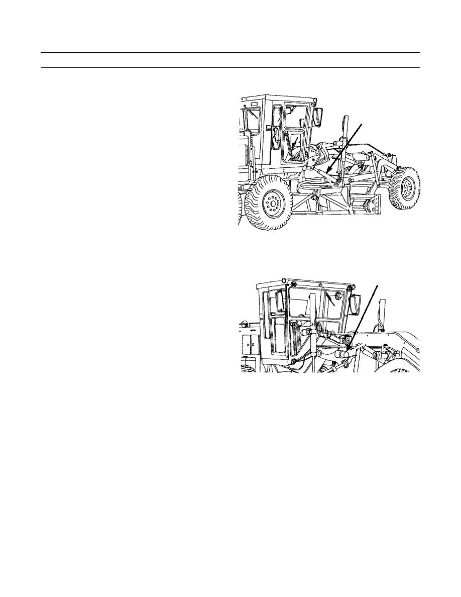
Blade Centershift Cylinder. The cylinder is
BLADE
attached to the circle assembly so that the draw-
CENTERSHIFT
bar and the blade can be moved to the right or to
CYLINDER
the left.
397-066
BLADE
b.
Blade Centershift Lock. This mechanical lock
CENTERSHIFT
is mounted on the blade lift bar. The lock pin is
LOCK
moved by an air operated valve in the housing.
397-067
c.
Blade Tip Cylinder. Attached to circle assembly and blade assembly so that the blade can be tipped forward or to
the rear. Hydraulic oil for tip cylinder operation is sent through the hydraulic swivel.
d.
Blade Lift Cylinder.
(1)
Each cylinder is attached to a blade lift arm and the circle assembly at each side of the frame. There is a lift
cylinder control lever and a right cylinder control lever in the cab.
(2)
The lift cylinders are used to raise or lower the blade. They are also used to rotate the blade lift arms to set
the blade angle for ditching and banking. Blade lift arms must be rotated with blade grounded and the cen-
tershift lock in the unlock position.
0003 00-35


