TM 5-3805-261-23-1
THEORY OF OPERATION - CONTINUED
0003 00
HYDRAULIC SYSTEM
0003 00
NOTE
Hydraulic system schematics are located in WP 0352 00.
1.
The hydraulic system provides a controlled flow of pressurized oil to the steering and implement circuits. It is a load
sensing hydraulic system, in which the pump works only as hard as necessary to meet system demands. If there is no
steering or implement demand, the pump conserves energy by reducing flow to what is needed for pump case drain
(internal leakage) and pressure to a minimum standby level of approximately 430130 psi (2,965896 kPa). This means
the pump works more efficiently and produces less heat in the hydraulic system.
2.
The main parts of the system are illustrated and explained in the following paragraphs.
a.
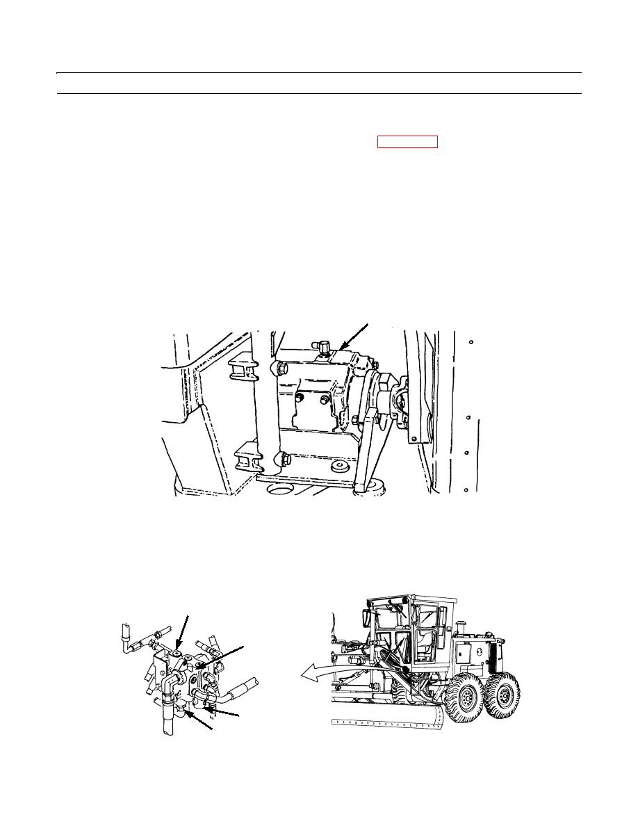
Hydraulic Variable Displacement Pump Assembly and Lines. Pump is mounted under the cab. Pump shaft is
driven by the engine. The variable displacement rear section draws oil from the hydraulic tank and provides oil
flow for steering, articulation, wheel lean, and earthmoving components. The constant displacement front section
circulates oil to the tank through the cooler, filter, and strainer.
HYDRAULIC VARIABLE
DISPLACEMENT PUMP
397-046
b.
Priority Valve. Valve is mounted under the cab, directly to the left of the variable displacement pump. Pressure oil
from the pump is routed to the priority valve, which regulates the flow of oil to the implement and steering circuits.
When there is a steering demand, the priority valve gives the steering circuit preference.
c.
Combination Valve. Valve is located at the left of the variable displacement pump. Oil from the variable displace-
ment pump flows through the combination valve when the engine is running. It then goes to the control valves for
the earthmoving components and to the steering metering valve. A hydraulic pressure unloading valve is included
for cold weather starting.
UNLOADING VALVE
PRESSURE
REDUCTION VALVE
397-047
0003 00-26


