TM 5-3805-261-20
PRINCIPLES OF OPERATION.
1-32.
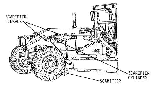
SCARIFIER ASSEMBLY (Figure 1-71). The scarifier assembly uses a hydraulic cylinder to move the scarifier
upward or downward. The scarifier control lever is located in the lever group at the right side of the steering console in the
cab. Refer to TM 5-3805-261-10 for scarifier operating instructions and control lever location. Refer to paragraph 1-29 for
description of control valve and lock check valve.
When the engine is running, the oil from the variable displacement pump goes through the relief and pressure reduction
valve through lines, to the control valve for the scarifier cylinder. The pressure of the oil in lines can get as high as the
pressure setting of the relief valve. When the control valve for the scarifier cylinder is not being used, the pressure of the
oil in lines is 2150 psi.
When the engine is running, and the scarifier is not being used, the pressure of the pump oil in lines to the control valve is
approximately 2150 psi. The oil in lines in passage is open to the tank and the pressure of the oil in these lines is the same
as the oil in the tank. Lock check valve stops the oil in the lines between valve and cylinder and the rod in the cylinder
cannot move. The pressure of the oil in lines is the same as the oil in the tank.
When the scarifier control valve lever is held in the LOWER position, the pump oil goes through control valve through lines
and lock check valve into the head end of cylinder. The oil in the head of cylinder pushes the piston and rod out of the
cylinder which moves the scarifier down. When more force is needed to lower the scarifier, there is an increase in the
pressure of the pump oil to the head end of cylinder. When the pressure of the pump oil goes to 1500 psi, the oil moves
the shuttle valve in the pump and the oil pressure from the pump can go to approximately 3500 psi.
Figure 1-71.
1-57 (1-58 blank)


