TM 5-3805-261-20
SENDING UNITS AND WARNING SWITCHES MAINTENANCE. (cont)
7-91.
Air Pressure Switch. (Sheet 2 of 3)
REMOVAL
NOTE
The
following
is
a
maintenance
procedure
for
one
air
pressure
switch. The maintenance procedure
for the other air pressure switch is
identical.
1.
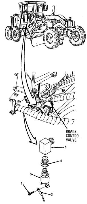
Remove two screws (1) from switch (3,
Figure 7-140) under right side of cab.
NOTE
All
wire,
cable
and
harness
assemblies must be tagged before
disconnecting to aid in installation.
2.
Disconnect two wire assemblies (2) at
switch (3).
3.
Remove switch (3).
4.
Remove bushing (4) and elbow (5) from
brake control valve.
CLEANING
Clean all parts. Refer to Chapter 2.
INSPECTION
Inspect all parts. Refer to Chapter 2.
Figure 7-140
Go to Sheet 3
7-222

