TM 5-3805-261-20
SCARIFIER ASSEMBLY MAINTENANCE. (cont.)
17-11.
Scarifier Assembly. (Sheet 2 of 9)
REMOVAL
NOTE
The
following
is
a
maintenance
procedure for the left-side scarifier
actuating
assembly.
The
maintenance procedure for the right-
side scarifier actuating assembly is
identical.
1.
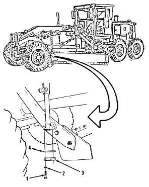
Remove two bolts (1), washers (2), cap (3)
and shim(s) (4, Figure 17-34).
2.
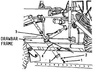
Position socket of link (5) over ball (6,
Figure 17-35) on drawbar frame.
3.
Install shim(s) (4), cap (3), two washers (2)
and bolts (1) to retain link (5) to ball (6) of
drawbar frame.
Figure 17-34.
Figure 17-35.
Go to Sheet 3
17-30


