TM 5-3805-261-34
STEERING MAINTENANCE.
8-7.
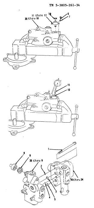
Combination Valve. (Sheet 9 of 9)
ASSEMBLY
NOTE
Place unloader valve in vise.
22.
Install items 11 thru 17 as an assembly, two washers
(7) and bolts (6) in items 35 thru 18 as an assembly
(Figure 8-32).
23.
Install screw (10).
24.
Lift lever (15, Figure 8-33) with a force of 25 lbs. Use
a dial indicating scale to measure force.
25.
Adjust screw (10). Turn screw (10) in or out until end
play of lever is 0.003 to 0.009 inches. Use dial indicator
to determine end play.
26.
Install nut (9) and boot (8, Figure 8-34).
27.
Install new preformed packings (5, 4, 3 and 2),
items 35 thru 6 as an assembly with items 70 thru
36 as an assembly and three bolts (1).
NOTE
Return 130G Grader to original
equipment condition.
End of Task
8-29/(8-30 blank)
Figure 8-34.
Figure 8-33.
Figure 8-32.